210 2231624

Dial Indicator Buyer's Guide
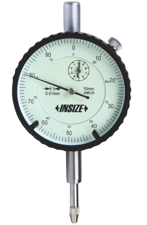
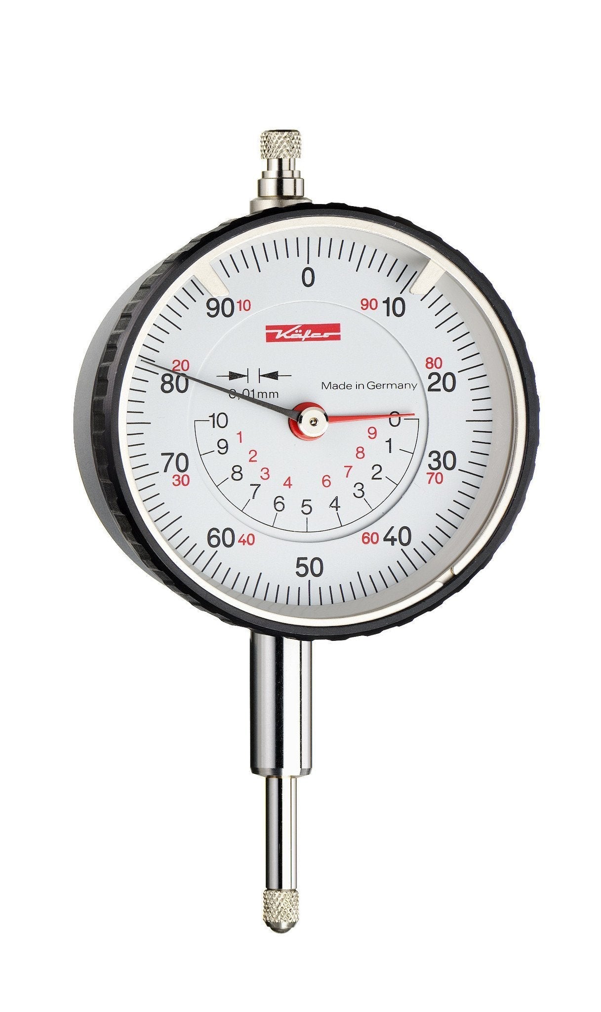
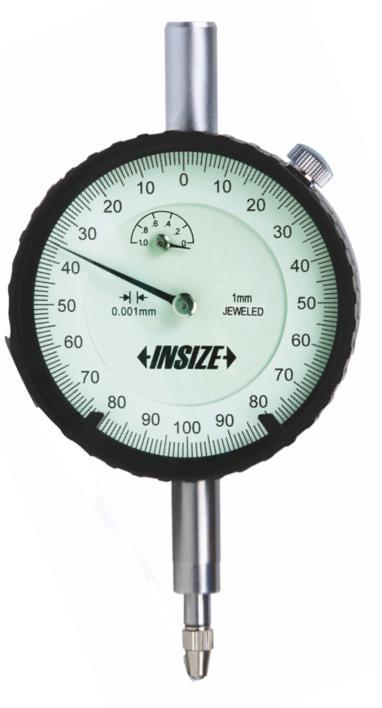
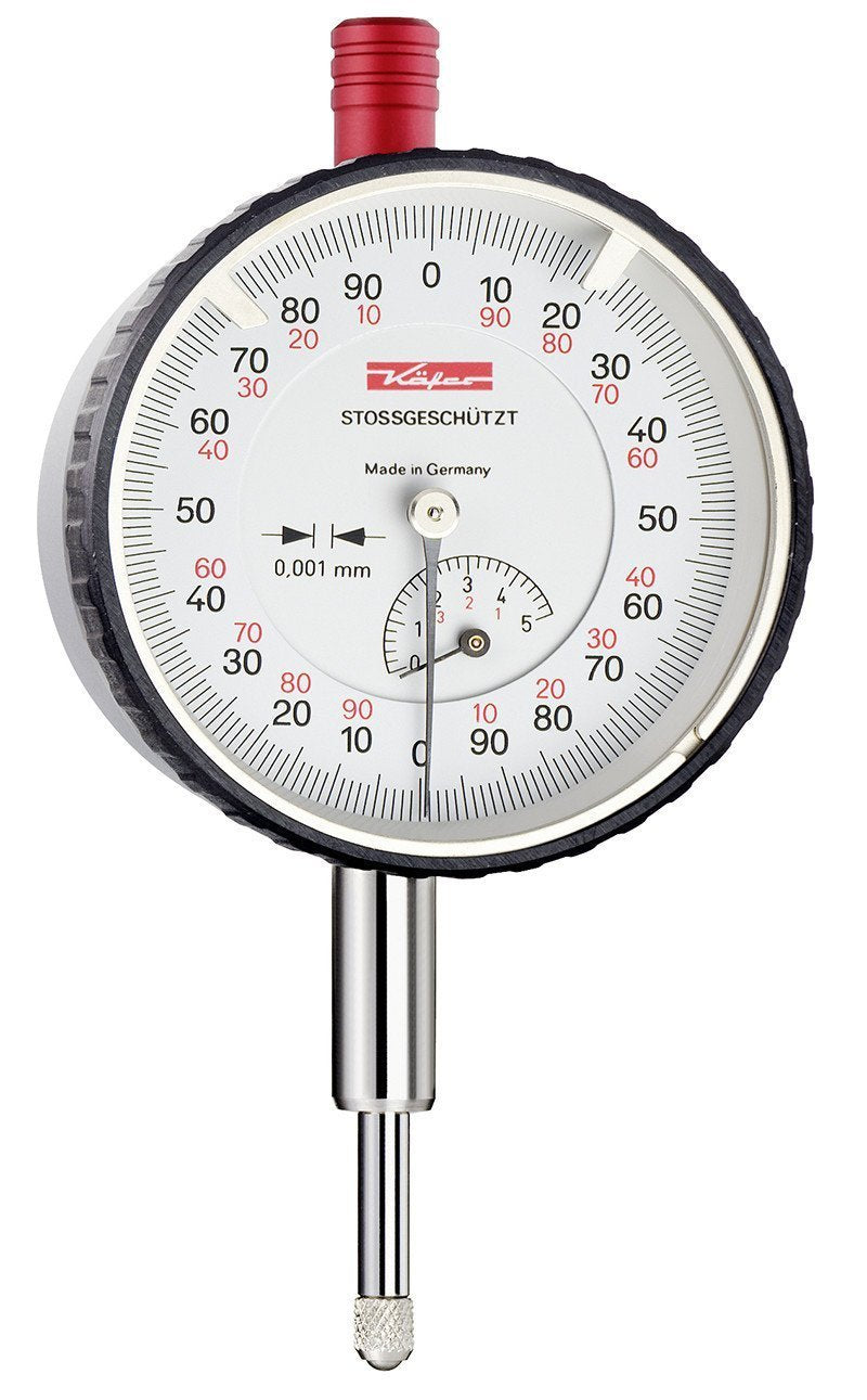
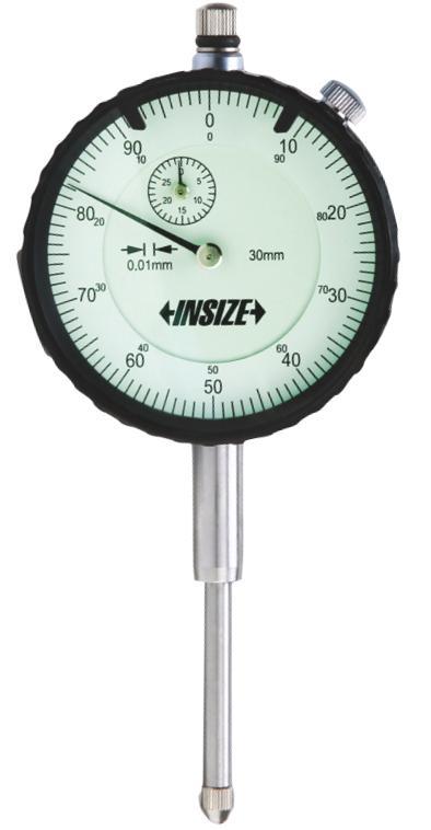
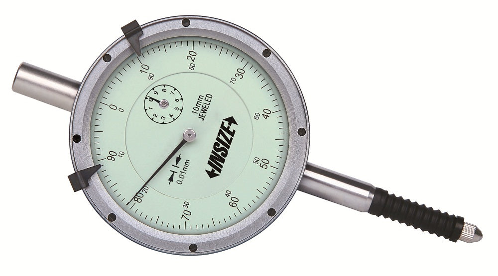
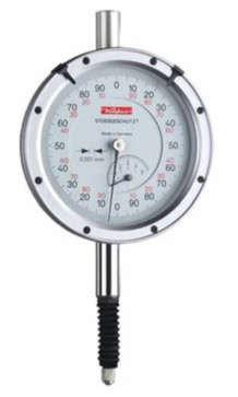
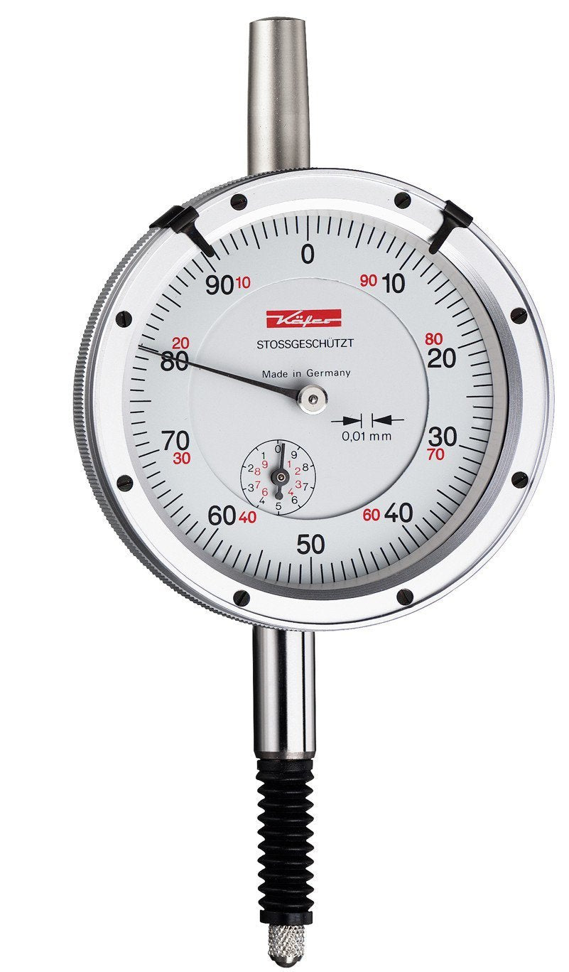
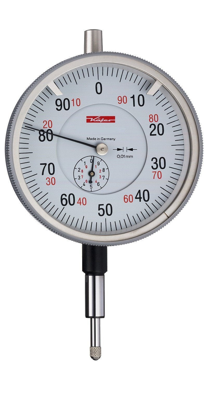
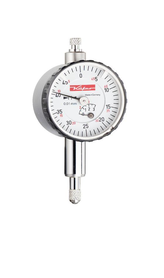
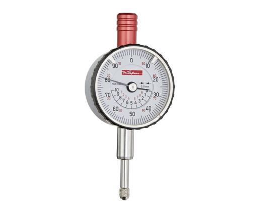
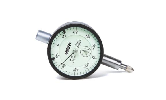
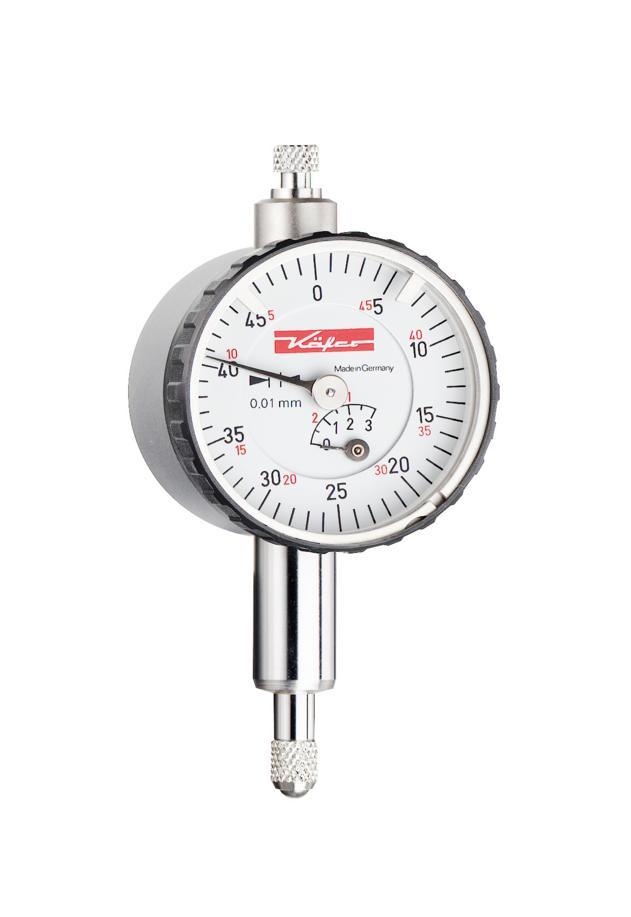
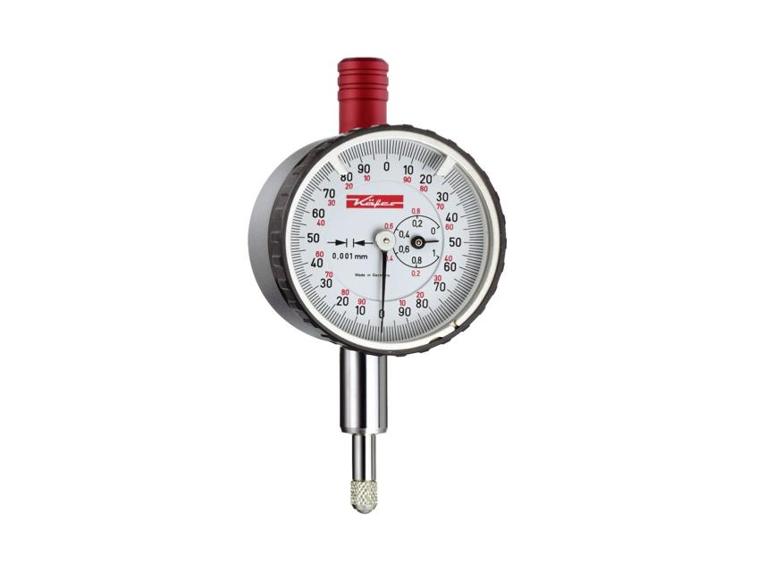
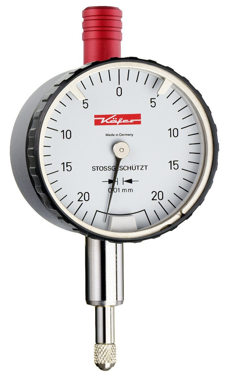
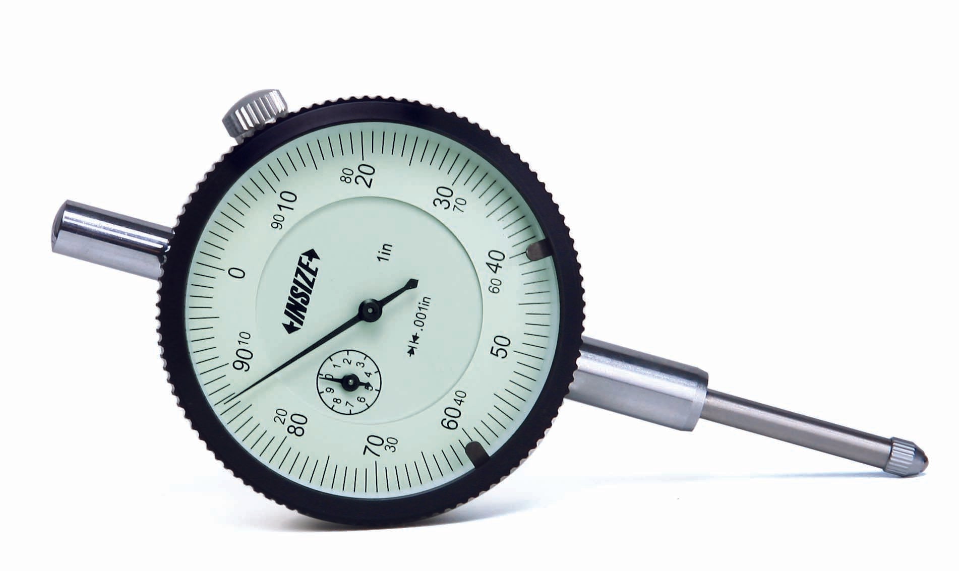
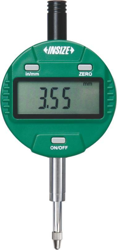
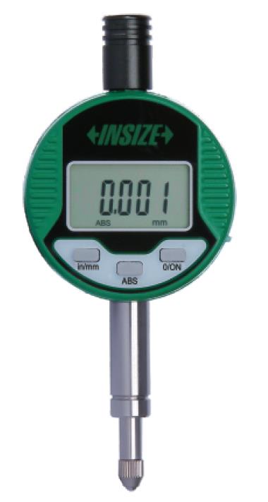
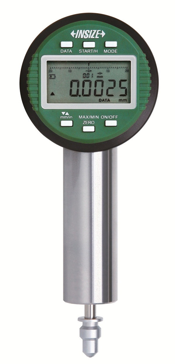
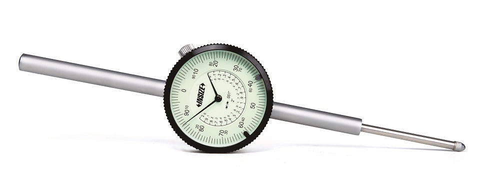
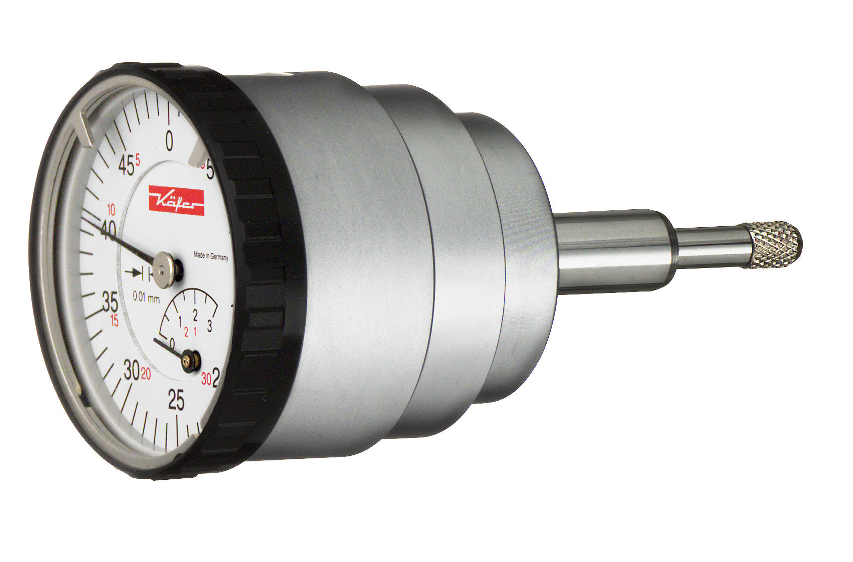
In the field of mechanical engineering the dial indicator is the instrument you use for high precision measurements of short distances (distance), amplifying them to make them more visible.
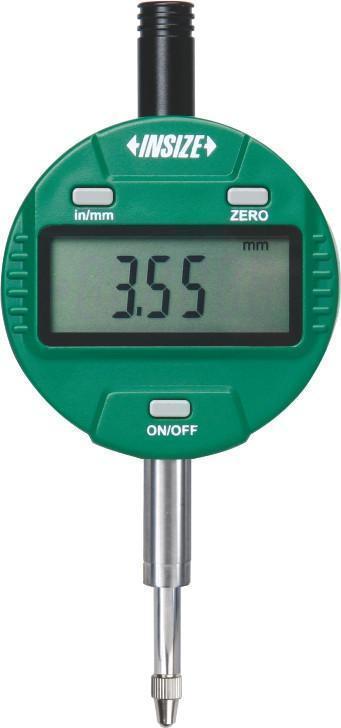
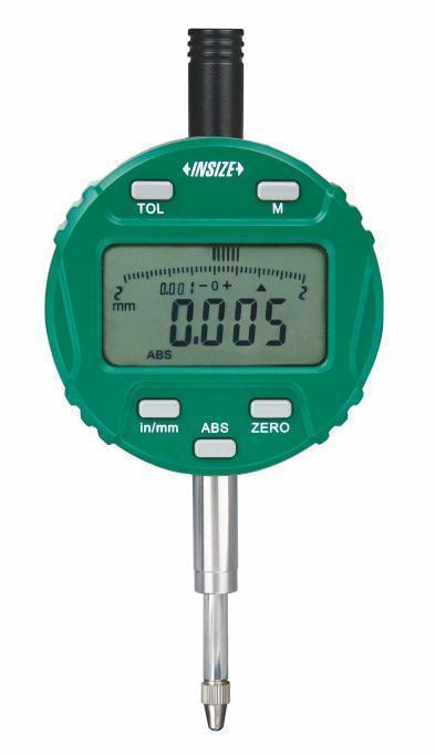
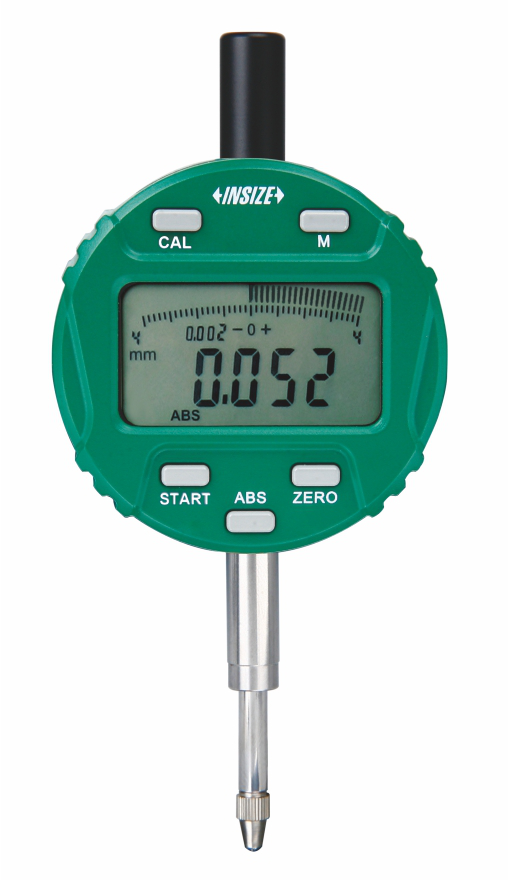
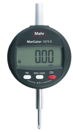
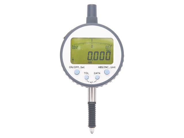
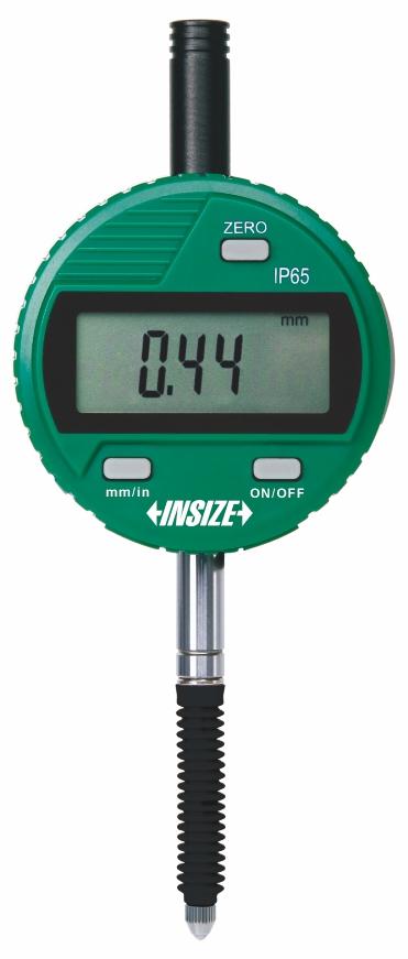
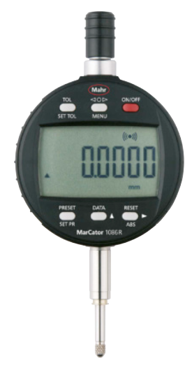
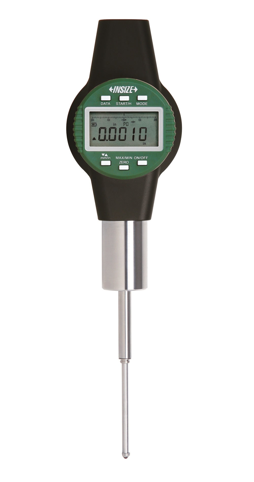
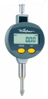
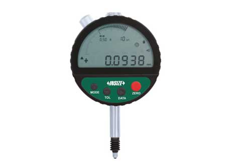
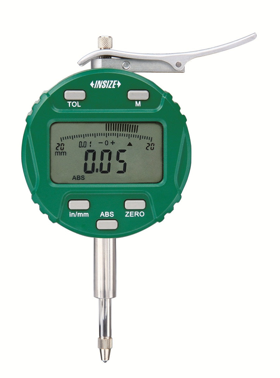
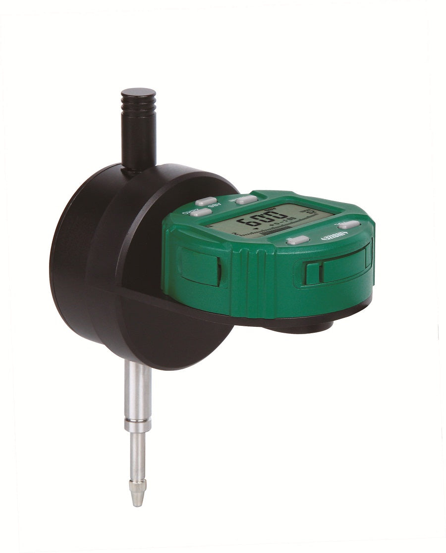
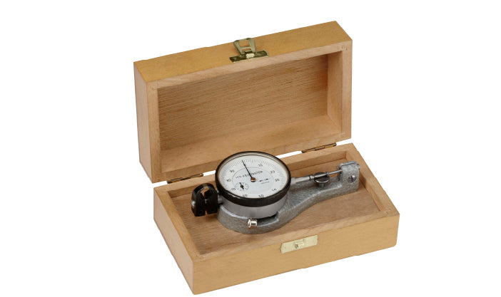
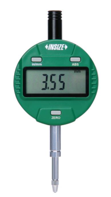
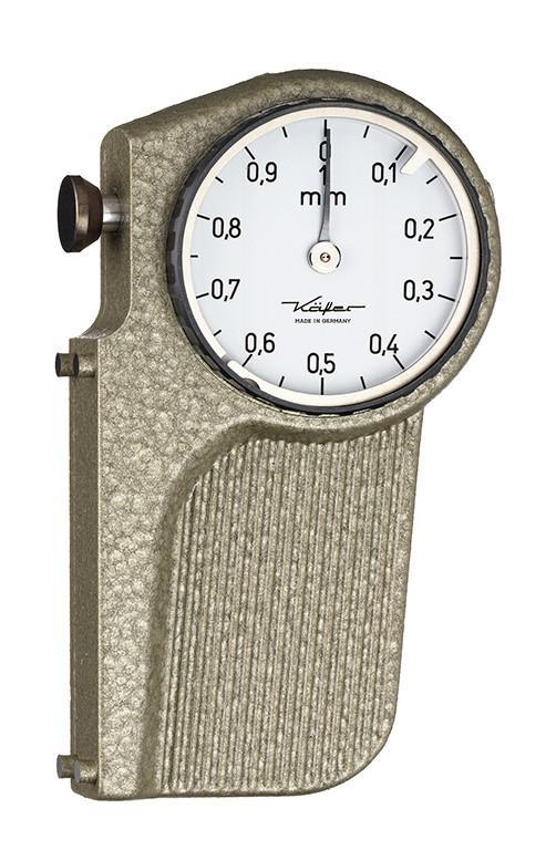
Dial indicators are divided into analog, digital. Also there are the test indicators used for centering machine tools, eccentricity control, roundness control.
The name in Latin comes from the concept of showing the user lengths which the naked eye cannot distinguish. (for example, a small height difference between two flat surfaces, a slight decrease in concentricity between two cylinders, or other small physical deviations).
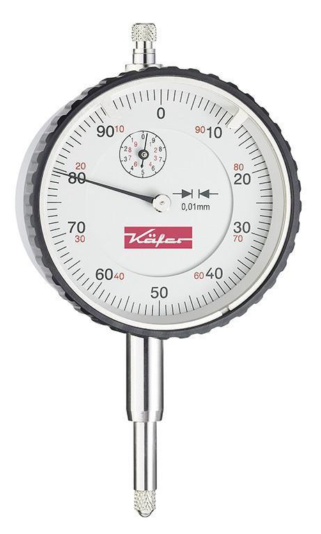
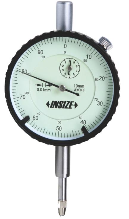
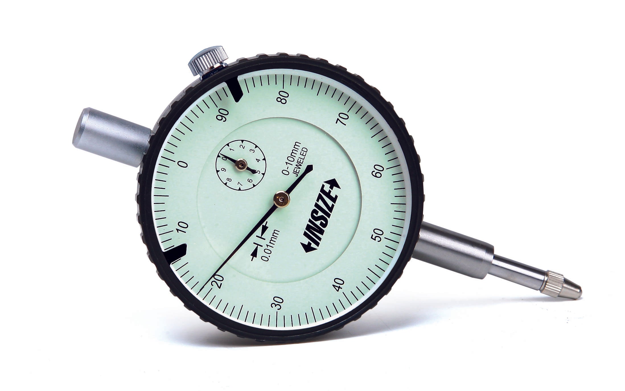
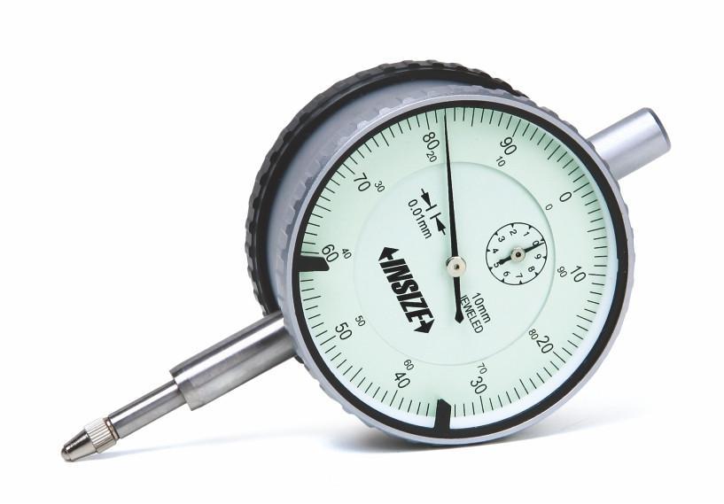
Dial indicators have the appearance of a common clock. They are also used for measuring tolerances on machined pieces, for checking the flatness of beams and in general for measurements involving small deviations.

A dial indicator is characterized by several technical characteristics:
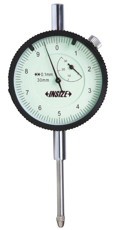
- Its stroke range (0-5mm, 0-10mm, 0-30mm, etc.)
- The reading of (0.01mm, 0.001mm etc.)
- Its size (The diameter of Ø40mm, Ø58mm etc.)
- The number of turns of the large pointer per stroke mm
- The second indicator which counts the number of revolutions of the first indicator.
- If it is "shockproof", (more durable internal mechanism to withstand the wear and tear of time.
- If it is Waterproof "Waterproof" IP protection
- Comparator ( Readings ±0.4mm)


Applications
- For checking tolerances on disc brakes. Typically 0.05mm or less
- For quality control in production.
- In the machine shop for calibrating and setting machines. (e.g. milling cutter centering)
- For centering the workpiece in the lathe chuck.
- In a variety of applications that require precision measurements outside the machine shop such as geology, physics, etc.
Screw fastening on a straight back watch. (Stem mounting)

Notes:
- Tolerances of the hole that the stem enters Ø8G7(±0.005-0.02mm)
- Special attention is needed when tightening. Over-tightening makes it difficult to move the movable spindle, thus creating an error in the measurement.
Fastening with a screw on a watch with a back (ear). (Lug mounting)

Notes:
- To minimize of the error of the sine effect ( cosine effect error ) the movable axis is recommended to be placed in the same line as the measurement.
Importance of placement

If the measurement is done in a horizontal position or even upside down, the measuring force of the needle is of course smaller. So it is necessary to check the repeatability of the measurements.
Maintenance
- Do not use lubricants (oil) for the moving spindle. Oil tends to collect dust thus making movement difficult.
- If the movement is not smooth use an alcohol pad.
- Before taking any measurement make sure the movement is smooth up and down.
The Cosine Effect
The measurement will have an error if the direction of the requested measurement does not coincide with the direction of the moving axis. This error is minimized by adjusting the pivot so as to minimize the angle θ.


