info@organametrisis.gr
210 2231624
210 2231624

Despite the improvement of machining means and measuring and inspection instruments, manufacturing a component with absolute accuracy is impossible to achieve because, quite simply, these machining means and inspection instruments cannot be manufactured without error.
A fit is the functional cooperation (connection, joining) of two parts (hole and shaft), e.g. a rolling bearing and a spindle (shaft), or a gearbox bearing seat; a crankshaft and the main bearings or the connecting rods; a keyway and a key; a prismatic guide and the sliding component (e.g. tool carriage); a power transmission shaft and a pulley or a gear (pinion), etc.
TOLERANCES
The difference between nominal and actual dimension is called DEVIATION or ERROR.
The deviation (error) from the nominal dimension, within permissible, clear, and standardized limits, is called the MANUFACTURING TOLERANCE.
For the standardization system I. S. O. (International Organization of Standardiza- tion - International standardization organization) we have:
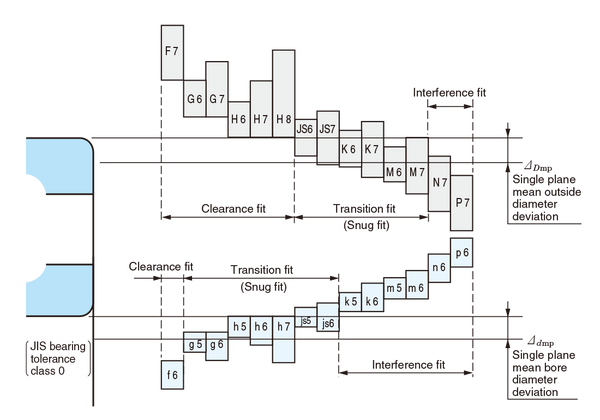
16 grades characterized by numbers from 1 to 16 and 21 classes with symbols A, B, C, D... etc. for holes (bores) and with a, b, c, d... etc. for shafts.
For practical and economic reasons it has been defined that, for a shaft and hole (bore) fit, one of the two, shaft or hole, must always have class h or H respectively.
In the first case we have a basic shaft fit and in the second case we have a basic hole (bore) fit.
The shaft always has class h. The holes, depending on the required fit, are characterized by the corresponding capital letter of the class. The largest dimension of the shaft is equal to the nominal, i.e. the maximum deviation is Am = 0 and the minimum Ae = TA (shaft tolerance zone).
Here we have:

Basic hole system.
The hole (bore) always has class H. The shafts, depending on the required fit, are characterized by the corresponding lower-case letter of the class and are manufactured larger or smaller than the hole. The smallest dimension of the hole is equal to the nominal, i.e. the minimum deviation is Be = 0 and the maximum Bm = TB (hole tolerance zone).
Here we have:

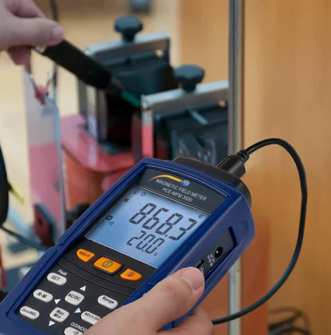
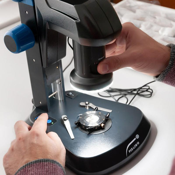
For the inspection of the components we manufacture, i.e. to verify whether their dimensions are within the tolerance zone, we use measuring instruments.
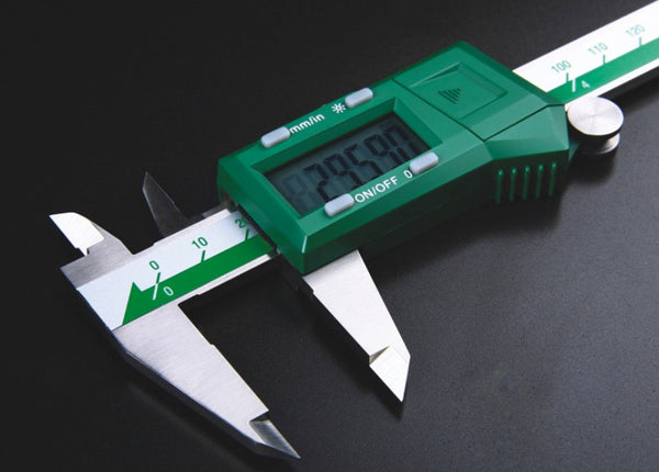
a) Variable length (calipers, micrometers etc.),
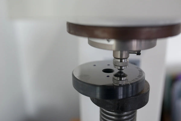
b) Fixed length, which are called LIMIT GAUGES maximum - minimum or limit gauges (Figure 1.a. & 1.b.).
During inspection with limit gauges, ERRORS are avoided and we achieve time savings.
They are the most user-friendly means for dimensional inspection of parts manufactured in series.
To verify whether the dimension being checked is within the tolerance zone, i.e. between the permissible maximum - minimum limits, we need two fixed lengths with these dimensions, one of which will be designated by the term "GO" and the other by the term "NO GO". We distinguish gauges into:
On each gauge the following are indicated:
A) The nominal dimension it checks in mmB) The fit classC) The fit gradeD) The tolerance limit values in microns (μm)E) Where applicable, the words "GO" and "NO GO".
Below we show various types of gauges: