Lathe Cutting Tools
Lathe Cutting Tools
Turning (Turning)
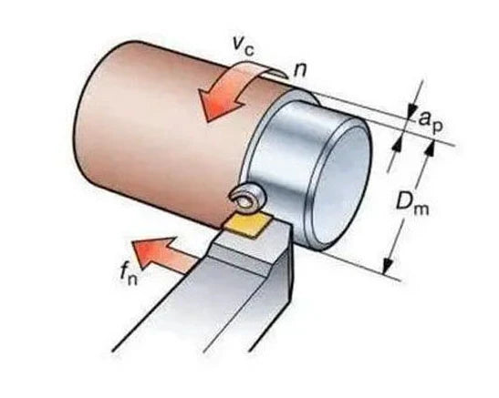
Turning is a basic metalworking method (and not only), where the workpiece rotates while the tool remains stationary. Machining is performed through the contact between the cutting edge and the rotating material. It is usually applied to components with rotational symmetry.
The tool movement can be either parallel (longitudinal) or perpendicular (transverse) to the axis of the workpiece. In this way, different shapes and surfaces can be achieved, such as cylinders, cones, or spherical forms.

Turning Categories
The turning process is divided into various types:
- External turning: machining is performed on the outer surface of the workpiece. It is distinguished into two different operations.
- Longitudinal machining (plain or straight turning): reduction of the outside diameter with movement parallel to the axis.
-
Facing (facing): the tool moves perpendicular to the axis, reducing the length of the workpiece.
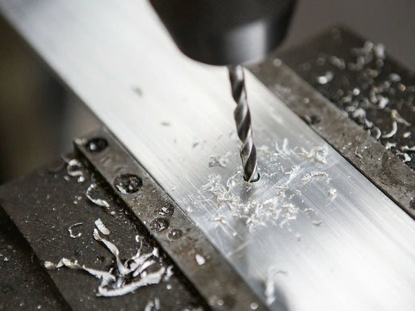
* Internal turning (boring): the cutting tool works inside an existing hole.
* Knurling (knurling): the machining operation that creates knurling (serrations) on cylindrical surfaces to prevent slipping
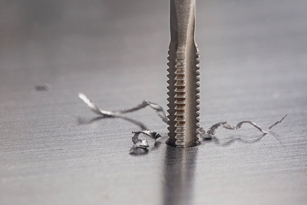
* Threading (thread cutting): creation of a thread with successive passes, external or internal.
* Grooving (grooving): production of grooves with predefined geometry.
* Parting (parting): cutting off the workpiece with full penetration of the tool.

Tool Selection
After the type of machining has been defined, the selection of the appropriate cutting tool follows. In turning, this selection mainly concerns choosing the cutting insert (insert), which must be suitable for the workpiece material, the type of machining, and the cutting conditions.
The geometric shape of the insert is a critical factor during selection, as it affects its mechanical strength, accessibility to the workpiece, and the overall machining performance. The angle between the sides of the insert determines the stress distribution during cutting and the ability to use the tool in different applications.
Insert selection is based on predefined geometric and functional characteristics, which are described by the ISO 1832 coding system. This coding includes the insert shape, the cutting angle, the clamping method, the dimensions, and the manufacturing tolerances.
ISO 1832
Each letter or number in the code corresponds to a specific parameter, allowing immediate identification and comparison of tools.

- C – Rhombic shape 80°
- N – Zero clearance angle - negative cutting (neutral clearance)
- M – Clamping method with clamp and central hole
- G – Standard manufacturing accuracy
- 12 – Side length 12 mm
- 04 – Thickness 4.76 mm
- 08 – Corner radius 0.8 mm
Correct interpretation of the ISO code is necessary for accurate tool selection, according to the requirements of the application.


Chipbreaker Selection (Chipbreaker)
The chipbreaker is the geometry we see on the "top" side of the insert. This geometry determines many parameters in cutting, such as chip formation and evacuation, heat management, and the distribution of cutting forces. Each geometry is used in a different application, depending on the Machined Materials (VDI 3323) and the application range

Chipbreaker selection is based on the following parameters:
- Type of machining (roughing, general machining, finishing)
- Machinable material (e.g., steel, stainless steel, cast iron)
- Depth of cut (ap) and feed (fn)
Indicatively:


Grade Selection
The insert grade refers to the composition of the carbide and its coating. Each grade is intended for a specific material to be machined and an application range
Indicatively:

Corner Radius Selection (Corner Radius)
The cutting radius - RE (nose radius) affects both surface quality and tool strength. A larger radius provides greater strength but increases cutting forces. In contrast, a small radius is more suitable for finishing operations with low power requirements. Also, as the radius increases, the minimum depth of cut Ap also increases.

Indicatively:
- 0.2–0.4 mm: for finishing
- 0.8–1.2 mm: for general machining
- >1.2 mm: for heavy machining and roughing
Selection is always made in combination with the other characteristics (chipbreaker, grade, type of application).