
Thread Gauges
This page continues the general guide to gauges, which covers GO and NO GO logic, Taylor's principle and the inspection of plain holes and shafts. Here the same logic is applied to threads, where acceptance is never decided by a single diameter.
The last part deals with the most important exception to the rule: taper pipe threads, where the gauge usually has no separate NO GO side at all.
Why a thread is not checked like a diameter
Whether two threads assemble does not depend on one dimension. It depends at the same time on the pitch diameter, the pitch, the flank angle and any deviation of the helical form.
A pitch error or a flank angle error does not change the actual pitch diameter, but it obstructs assembly exactly as if it had. This combined effect is called the virtual pitch diameter, and it is what a thread gauge really measures.
The question it answers
A thread gauge does not answer "what is the pitch diameter?". It answers "will this thread assemble correctly with its mating part?".
GO and NO GO on a thread


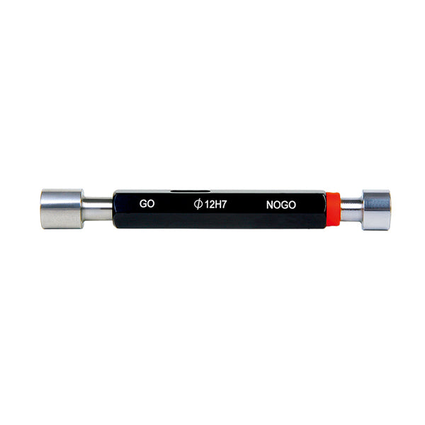
GO
Has the full thread form and must enter by hand over the whole specified length, without tools and without excessive force.
It checks the virtual pitch diameter, that is the maximum material condition together with any pitch and flank angle errors. If it does not assemble, the thread is rejected.
NO GO
Has a shorter engagement length and a truncated form, so that it responds to the pitch diameter alone and not to the form.
It may engage from either end, but by no more than two full turns. More than two turns means rejection.
A red mark on the body or the handle always identifies the NO GO side.
What a thread gauge does not check
The most common mistake is to assume that the gauge covers the whole thread. It covers the pitch diameter and the form that goes with it.
When the drawing calls out the major or minor diameter, you need plain gauges or a numerical measurement, for example a thread micrometer.
The five possible results
Combining the two sides gives five outcomes. Only one of them is a clean pass.
| Workpiece | GO | NO GO | Decision |
|---|---|---|---|
| Below tolerance | Does not enter | Does not enter | Reject, the thread is too tight |
| At the lower limit | Just enters | Does not enter | Accept, at the edge of tolerance |
| Within tolerance | Enters freely | Up to two turns | Accept |
| At the upper limit | Enters freely | Exactly two turns | Accept, at the edge of tolerance |
| Above tolerance | Enters loosely | More than two turns | Reject, the thread is too open |


The exception
Taper pipe threads
Everything above assumes that the thread diameter stays constant along the axis. On a taper pipe thread the diameter changes progressively, with a typical taper of 1:16 on diameter. As the joint is screwed together the engagement tightens and contact builds up on the thread flanks themselves.
That changes the inspection problem completely. Every axial position corresponds to a different diameter, so the size is meaningless without a reference plane. That reference is the gauge plane.


Why there is no NO GO side
A taper gauge needs no second body at a different diameter, because the gauge itself passes through every diameter as it screws in. The two functional limits are expressed instead as two axial positions, in the form of tolerance steps, scribed lines or the face of the gauge.
The NO GO criterion is therefore not abandoned. It is simply expressed differently: rejection means the workpiece face comes to rest outside the permitted zone.
Which taper threads you will meet
The three main systems share the same 1:16 taper, but they are not the same thread. Their gauges are not interchangeable.
| System | Form | Sealing | Inspection |
|---|---|---|---|
| ISO 7 BSPT | 55° profile. R external taper, Rc internal taper, Rp internal parallel. | With a suitable jointing medium applied on the thread. | Plug and ring gauges to ISO 7-2. |
| NPT | 60° profile, with flat truncated crests and roots. | Requires a thread sealant for a pressure tight joint. | L1 plug for internal, L1 ring for external. |
| NPTF | 60° profile, with specially controlled crests and roots. | Dryseal, through controlled metal to metal contact. | L1 plus L3 plug or L2 ring, with crest check. |
Do not confuse G with R
The G thread to ISO 228, also known as BSPP or GAS, is parallel, not tapered. It seals on a separate face, with a washer or an O ring, and it is checked with an ordinary GO and NO GO pair.
The R thread to ISO 7, known as BSPT, is tapered. The two will start together for the first few turns, which is exactly why they get mixed up in the field.
| Nominal size | ISO 7 · BSPT, threads per inch | NPT, threads per inch |
|---|---|---|
| 1/8" | 28 | 27 |
| 1/4" and 3/8" | 19 | 18 |
| 1/2" and 3/4" | 14 | 14 |
| 1" to 2" | 11 | 11.5 |
The nominal size refers to the pipe, not to any diameter you can measure on the thread. A 1/2" thread has an outside diameter of roughly 21 mm.
How the check is carried out
Warning
Tightening with a wrench is not an inspection method. On a taper thread it artificially shifts the reading, it can pass a defective part, and it wears the gauge.
What each system inspects
ISO 7R, Rc and Rp
Internal Rc and Rp threads are checked with the taper threaded plug gauge, external R threads with the full form taper ring gauge. The part is accepted when its end face lies between the tolerance steps, or flush with one of them.
ISO 7-2 also defines a second stage, using plain taper gauges, for the available length of engagement and the geometry of the taper itself.
NPTThe L1 gauge
The L1 gauge checks the pitch diameter at the hand tight engagement position. The plug gauge is made with two steps, a GO step and a NO GO step, and the reading is taken against them. On a ring gauge the reading is taken against the face of the ring.
An L1 gauge on its own does not confirm everything over the L2 and L3 lengths, which is where the joint is finally made up.
NPTFL1, L2, L3 and crest check
Because sealing comes from metal to metal contact, inspection is stricter. L1 covers the hand tight region. An L2 ring gauge is added for the external thread and an L3 plug gauge for the internal one, so that the wrench tight region can be assessed against the first reading.
Depending on the gauging class, crest check gauges are also used for the truncation of crests and roots.
Wear and calibration
A thread gauge wears on the thread flanks, which is precisely where the measurement happens. The GO side engages fully on every part, so it wears fastest.
On taper gauges wear matters even more, because it translates directly into a shift of the reading position. A few hundredths of a millimetre of wear will visibly move where the workpiece face comes to rest.
Every gauge should carry a unique identity, a defined checking interval and a documented calibration status.
Which gauge do you need
| Thread | Internal | External |
|---|---|---|
| Metric M | Thread plug gauge | Thread ring gauge |
| G, BSPP parallel | GAS PIPE plug gauge | GAS PIPE ring gauge |
| R, BSPT taper | Made to order | BSPT ring gauge |
| NPT taper | NPT plug gauge | NPT ring gauge |


Conclusion
On a parallel thread the decision comes from two gauges at two different diameters. On a taper thread it comes from one gauge and two positions. The principle is unchanged: you are checking whether the part falls between two limits.
The right question is not whether the gauge passes, but which standard it follows, which feature it actually checks and which face serves as the reference.
← All guides

Related guides
GaugesΠώς οι ελεγκτήρες GO και NO GO μεταφέρουν τα όρια της ανοχής στο σημείο ελέγχου, χωρίς ανάγνωση αριθμού.
FitsΠώς η σχέση των ανοχών άξονα και τρήματος δίνει χάρη ή σύσφιξη, με το σύστημα ISO 286 και τον έλεγχο go/no-go.
How to identify the thread on an old boltΠώς αναγνωρίζεται ένα άγνωστο σπείρωμα με παχύμετρο και σπειρώμετρο, σε πέντε βήματα.
StraightedgesChecking straightness and flatness of surfaces per DIN 874.
Gauge BlocksStandard length gauge blocks for calibration and setting.
Precision Squares DIN 875Checking 90° squareness with precision squares.
Κατηγορίες Ακρίβειας Γωνιών: DIN 875Accuracy grades of 90° squares per the DIN 875 standard.
Surface PlatesGranite or cast-iron reference plates for flatness checking.