
Gauges
Gauges are dimensional inspection tools used to establish quickly whether a part falls inside its specified tolerance limits. They normally display no numerical value. They return an accept or reject result, according to whether the part mates correctly with the gauge.
A gauge is not a measuring instrument
A caliper or a micrometer measures a dimension and hands you a number, say 24.982 mm. A gauge works the other way round. It embodies a defined size, a limit or a particular geometric form, and is used to check whether the part conforms to it.
That is why most gauges carry no scale. The operator never reads a size. They check whether the gauge enters, does not enter, fits or fails to fit as intended.
The method earns its place in production, where many identical parts have to be checked fast and with as little operator judgement as possible.
The question it answers
A gauge does not answer “what is the size?”. It answers “is the size within the permitted limits?”.
Master and reference gauges
A master gauge embodies a known size to a high degree of accuracy. It is used to set comparative instruments, to check other gauges, or to verify a measuring system as a whole.
Its job is not usually to inspect large numbers of production parts directly. It is the reference against which some other device is set or checked.

Limit gauges
Limit gauges embody the permitted limits of a dimension. They are used in pairs, or combine two gauging surfaces in a single body. Either way they confirm that the dimension lies between the lower and the upper permitted limit, with no need to measure its actual value.
GO
Must mate with the part over the whole specified length, under the weight of the gauge or with light hand pressure. Excessive force is never permitted.
NO GO
Must not mate with the part beyond the amount allowed by the applicable procedure or standard.
Exactly how the two sides behave depends on whether an internal or an external dimension is being checked.
Taylor’s principle
The governing design rule for limit gauges was set out by William Taylor. The GO gauge checks the maximum material condition and should, as far as is practical, check every feature that affects the fit at the same time. That is why it normally has full form and engages the whole gauged length.
The NO GO gauge checks the least material condition. It is usually shorter, or restricted in its contact area, so that it checks one feature at a time.
A long cylindrical GO gauge, for instance, does not merely check a local diameter of the bore. It can also reveal form or alignment errors that would prevent the parts going together in service. Taylor’s principle is the reason the GO side is normally the longer one and the one that does most of the work.
Checking a bore with plug gauges
For a bore to be accepted, the GO plug must enter over the whole specified length while the NO GO plug must not enter. If the GO side will not go in, the bore is either too small or has a form defect that would block assembly. If the NO GO side does go in, the bore is larger than the upper limit.
The reason lies in how much material the part carries. In a bore, material is at its greatest when the diameter is at its smallest permitted value. So the GO plug corresponds to the lower limit of the diameter, and the NO GO plug to the upper limit.

Gauges for plain cylindrical bores are known as plug gauges. They come as single ended, double ended or progressive. On a double ended gauge the GO and NO GO ends sit on either side of the same handle. The GO end is usually the longer of the two, because it checks the whole functional length of the bore. The NO GO end is shorter and often carries a red band.
On the progressive type both limits sit on the same end. The GO section enters first, and the NO GO section behind it must not. Plug gauges for large diameters may be lightened or built in sections to keep the weight down.
Checking a shaft with snap and ring gauges
On a shaft, the GO gauge corresponds to the upper limit of the diameter and must pass over the part. The NO GO gauge corresponds to the lower limit and must not pass. If GO will not pass, the shaft is above the permitted limit or has a form error. If NO GO passes, the shaft is below the permitted limit. This is because on a shaft the maximum material condition is the largest permitted diameter.
Ring gauges
Ring gauges enclose the entire external cylindrical surface of the shaft. The GO and NO GO limits are normally handled by two separate rings. The full circular surface of the GO ring gives a functional check of the diameter and can reveal form errors that would prevent assembly.
Snap gauges
Snap gauges are applied to the shaft from the side, which makes them much faster over a large batch. They come as single, double or progressive. On the progressive type the GO and NO GO limits sit on the same side.

Because a snap gauge does not enclose the whole surface of the shaft, the check may need repeating at several angular positions in order to catch a departure from roundness.
Adjustable gauges
Adjustable gauges have movable contact faces and can be set to different limit sizes within a given range. They are set using suitable reference standards. Their advantage is that one gauge covers more than one dimension, and that wear can be compensated for.

Watch out
Adjustability demands more careful verification. An adjustable gauge must not be used unless it has been set and checked against a suitable reference standard.
Taper gauges
Taper gauges are used to check internal and external conical surfaces. They come as taper plug gauges and as taper ring gauges.
Checking a taper is never about a single diameter. It examines the relationship between diameter, angle and axial position. Depending on the design, acceptance may be judged from limit marks, from how far the gauge enters, or from the contact pattern between the surfaces.
Thread gauges
Threads call for dedicated gauges, because a thread fit never hangs on a single diameter. It is governed by the pitch diameter, the pitch, the flank angle and departures from the helical form.


The GO thread gauge has the full profile and checks whether the thread will actually assemble. It must run on by hand over the whole specified length, without undue force.
The NO GO gauge usually has a shorter engagement length and a modified profile. Its job is mainly to confirm that the pitch diameter has not passed its limit. How far it may engage is set by the applicable standard and the type of thread. For routine checking of metric threads, engagement of up to two full turns is the criterion commonly used.
Checking with a thread plug or thread ring gauge does not always take the place of checking the major and minor diameters separately. Where the drawing calls for those features, plain gauges or numerical measurements are needed as well. More in the guide to thread gauges.
What is marked on a gauge
Markings vary with the type of gauge and the standard applied. Typically you may find:
What each marking means must be confirmed against the certificate and the instructions for that particular gauge.
Using a gauge properly
The reliability of the check rests as much on how the gauge is used as on the gauge itself.
Gauge tolerance and wear
A gauge is not a theoretically perfect size. It has a manufacturing tolerance of its own, and an uncertainty of its own.
The GO side is used more often and comes into fuller contact with the parts, so it wears faster. Depending on the system applied, a wear allowance may be provided for it. The NO GO side is used less and usually never enters the part fully, so it wears less.
Wear can shift the real limit being applied and let unsuitable parts through. That is why gauges need a unique identity, a defined checking schedule, and a documented calibration or verification status.
Gauge tolerances and wear allowances are not a fixed percentage for every application. They follow from the type of gauge, the tolerance class and the standard applied.
What a gauge cannot tell you
An accept result does not mean you know the actual size of the part. A gauge will not tell you:
Setting up the process, tracking it statistically and investigating a reject all call for numerical measurement with a suitable instrument.
In short
Gauges carry the tolerance limits off the drawing and put them at the point of inspection. They allow a fast, repeatable accept decision with no number to read.
A simple output does not make a simple tool. A gauge is only as reliable as its design, its relationship to the limits on the part, Taylor’s principle, its wear, its calibration and the way it is handled.
← All guides


Related guides
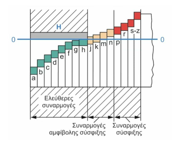
FitsΠώς η σχέση των ανοχών άξονα και τρήματος δίνει χάρη ή σύσφιξη, με το σύστημα ISO 286 και τον έλεγχο go/no-go.
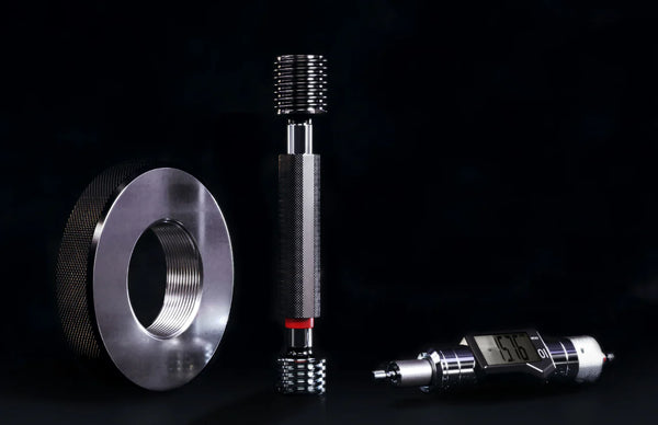
Thread GaugesGO/NO-GO gauges for checking internal and external threads.
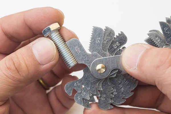
How to identify the thread on an old boltΠώς αναγνωρίζεται ένα άγνωστο σπείρωμα με παχύμετρο και σπειρώμετρο, σε πέντε βήματα.
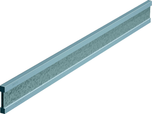
StraightedgesChecking straightness and flatness of surfaces per DIN 874.
Gauge BlocksStandard length gauge blocks for calibration and setting.
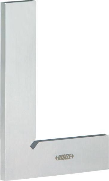
Precision Squares DIN 875Checking 90° squareness with precision squares.
Κατηγορίες Ακρίβειας Γωνιών: DIN 875Accuracy grades of 90° squares per the DIN 875 standard.
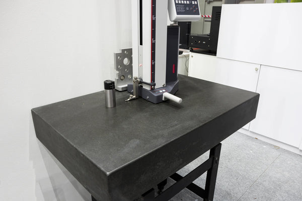
Surface PlatesGranite or cast-iron reference plates for flatness checking.