
Fits
How the relative position of two tolerance zones, one on the hole and one on the shaft, decides whether the parts turn freely or lock together.
What a fit is
A fit is the relationship between two mating parts: a shaft, the enclosed or male member, and a hole, the enclosing or female member. The surface where the two meet is the mating surface.
Both members always carry the same basic size. What differs is their tolerances, and those alone decide whether one part runs freely inside the other, slides with no play, or has to be pressed in. A fit is therefore inseparable from tolerance.

Why tolerances exist: interchangeability
No part is ever produced at exactly its basic size. Every part comes out somewhere inside a tolerance zone, a band of acceptable dimensions.
In volume production the shaft and the hole are made separately, by different people, on different machines, in different places and at different times. For them to assemble correctly with no fitting work at the bench, each one has to land inside limits agreed in advance. That property is called interchangeability, and it is the reason the whole system of limits and fits exists.
Clearance and interference
The governing quantity is clearance, defined as hole size minus shaft size. Its sign is what names the relationship:
Clearance (positive)
The hole is larger than the shaft. A gap remains, so the parts can move relative to each other.
Interference (negative)
The shaft is larger than the hole. Interference is simply negative clearance.
Because each member owns a whole tolerance zone rather than a single value, every fit is described by two extremes, obtained by pairing the worst limits against each other:
Maximum clearance = largest hole − smallest shaft
Minimum clearance = smallest hole − largest shaft
The diagrams below are labelled in Greek: Χμ is the maximum clearance and Χε the minimum clearance.
The four kinds of fit
Depending on where the two tolerance zones sit relative to one another, and therefore on how much freedom is left between the members, four cases arise. The four diagrams are meant to be read against each other: only the position of the blue shaft zone changes relative to the hole zone.
01
Clearance fit

The hole is larger than the shaft in every possible pairing, so even the minimum clearance stays positive. The parts slide and rotate freely.
02
Sliding fit

The limiting case of the clearance fit, where the two zones just touch at the zero line and the minimum clearance falls to zero. It allows assembly and axial sliding by hand, but not continuous rotation under load, since in the worst pairing no gap is left to carry a lubricant film.
03
Transition fit

The two zones overlap, so the minimum clearance turns negative, meaning interference, while the maximum clearance stays positive. Each pair ends up either slightly loose or slightly tight. It gives accurate centring and stays a joint you can take apart.
04
Interference fit

Even the smallest permissible shaft is larger than the largest permissible hole, so interference is always present. Assembly needs a press or a temperature difference, and produces a practically permanent joint that transmits torque with no key.
ISO groups these into three classes (clearance, transition, interference), since the clearance and sliding cases together make up the clearance fit.
Worked example
The Ø60 pair from the first drawing
Shaft Ø60 +0/−30 µm, that is 59.970 to 60.000 mm. Hole Ø60 +15/−8 µm, that is 59.992 to 60.015 mm.
Max clearance = 60.015 − 59.970 = +45 µm
Min clearance = 59.992 − 60.000 = −8 µm
Maximum clearance positive, minimum clearance negative: this is a transition fit. On the shop floor some pairs will go together with a little play and others will need a light tap.
The ISO 286 system of limits and fits
In practice fits are not invented case by case· they are specified through the standard ISO 286 code. Each tolerance zone is described by two things:
Where the zone sits relative to the basic size, given by a letter: the fundamental deviation. There are 28 positions, upper case for holes (A to ZC) and lower case for shafts (a to zc). H and h correspond to a fundamental deviation of zero.
How wide the zone is, given by an IT grade (International Tolerance grade). There are 20 grades, from IT01 (extremely tight) to IT18 (very coarse)· the lower the number, the more precise the work.
A dimension is then written as Ø32 H7 for the hole or Ø32 g6 for the shaft. Every value in the system applies at the reference temperature of 20 °C· with tight grades and large sizes, how far the inspection room drifts from that temperature genuinely matters.
Basic hole system (H) and basic shaft system (h)
To arrive at the fit you want, you hold one member fixed and vary the other.
Basic hole system (H)
By far the more common of the two. The hole carries a fundamental deviation of zero, so its lower limit coincides with the basic size and rests on the zero line, and the character of the fit is set entirely by the shaft. It is also the cheaper route: the hole is produced with standard drills and reamers and checked with standard plug gauges, while the shaft, which is easy to turn or grind to any size, does all the varying.


Basic shaft system (h)
Here the shaft carries the zero fundamental deviation, so its upper limit coincides with the basic size, and the hole is varied instead. It is the less common arrangement and earns its place when the outside diameter arrives finished and is not machined at all: drawn or ground bar stock, one long shaft carrying several components (pulleys, gears, collars, spacers), or the outer ring of a rolling bearing seated in a machined housing bore.


Common fits and where they are used
Basic hole system, the preferred ISO 286 combinations.
| Code | Type | Typical use |
|---|---|---|
| H11/c11 | Loose running | Joints with wide clearance, exposed to dirt or large temperature swings |
| H9/d9 | Free running | Bearings with generous clearance, where positional accuracy is not critical |
| H8/f7 | Close running | Lubricated plain bearings at moderate speeds and loads |
| H7/g6 | Sliding | Accurate location with free movement and very little play |
| H7/h6 | Locational clearance | Assembly and disassembly by hand, accurate positioning |
| H7/k6 | Locational transition | Accurate centring, still separable with a light tap |
| H7/n6 | Tight transition | Centring with no play, assembled under a press |
| H7/p6 | Locational interference | Permanent seating with accurate location, light torque transfer |
| H7/s6 | Medium drive | Torque transmitted without a key, pressed or shrink fitted |
The same fit characters exist in the basic shaft system with the roles reversed: C11/h11, F8/h7, G7/h6, K7/h6, P7/h6 and so on.
The common misconception
A fit is not the tolerance of one part· it is a property of the pair. It emerges from how the two zones relate to each other, which is why two parts that are each perfectly “in tolerance” can still produce the wrong fit if they were not specified together. For the same reason the code is always written as a fraction, H7/g6, never as a single term.
Inspecting fits with go/no-go gauges
Since a fit comes out of two parts, you inspect it by checking the hole and the shaft separately against their own limits: if both members are within tolerance, the intended fit follows automatically. In volume production that check is not made by measuring the actual size, but with limit gauges, plug gauges for holes and snap gauges for shafts.
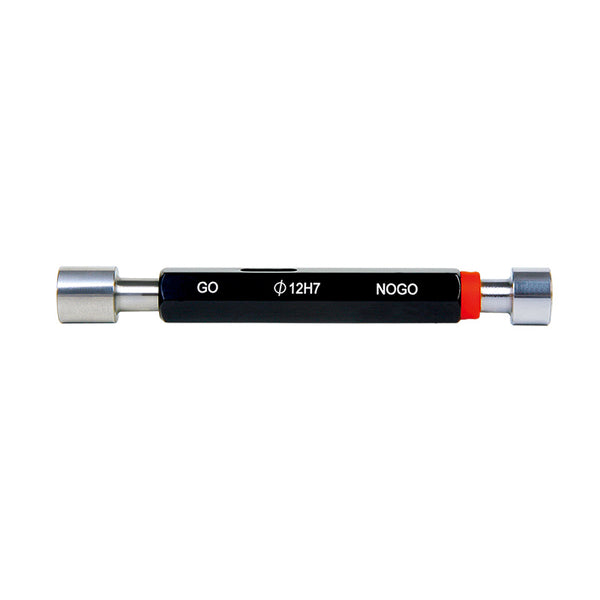
A limit gauge has no scale. It does not tell you what the dimension is, only whether it falls inside the permitted limits. It has two ends of fixed size:
GO
Corresponds to the maximum material limit: the smallest permitted hole or the largest permitted shaft.
NO GO
Corresponds to the least material limit: the largest permitted hole or the smallest permitted shaft.
The part is accepted when the GO end passes under its own weight, with no force applied, and the NO GO end does not. That confirms the dimension lies between the two limits without reading a single number. Different gauge types serve the two members.


Gauges come in single or double form, with the two ends separate or combined in one tool. Each gauge is marked with the basic size, the fit class and grade (for example Ø60 H7), the limit values in µm and often the words GO and NOT GO. Gauges carry manufacturing tolerances of their own, and the GO end gets an additional wear allowance, since it is the end that rubs on every single check.
Their design follows Taylor’s principle (1905): the GO end checks the maximum material condition and should check as many features at once as possible, meaning size, roundness and straightness together, which is why it has full form and full length. The NO GO end checks the least material condition and only one feature at a time. In practice the GO end is the decisive one: if it does not pass, the part is rejected without exception, because it will simply not assemble.
Thread tolerances and thread gauges
The same logic carries over to screw threads, except that the fit no longer hangs on a single diameter but mainly on the pitch diameter, together with the pitch itself and the flank angle. A tolerance system parallel to ISO 286 applies here too: for ISO metric threads (ISO 965) the class is written as 6H for the internal thread (nut) and 6g for the external one (bolt), where the number gives the grade and the letter the position of the zone, upper case for internal and lower case for external threads, exactly as with plain features. A typical bolt and nut pairing is therefore written 6H/6g.

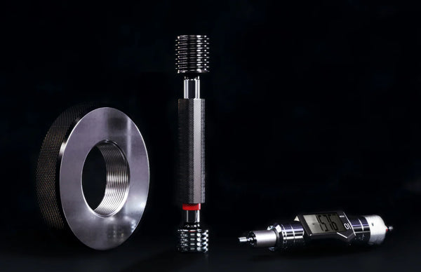
Inspection is again done with go/no-go gauges, in a dedicated form: thread plug gauges for nuts and thread ring gauges for bolts. The GO end has the full profile and full length and must run on freely along the whole thread, confirming that the part will assemble. The NO GO end has a truncated profile and checks the pitch diameter alone· under ISO 1502 it may not engage more than two full turns, while American practice (ASME B1.2) allows up to three on certain lengths. Inch threads follow an equivalent class system, 2A and 3A for external threads, 2B and 3B for internal ones.
← All guides

Related guides
GaugesΠώς οι ελεγκτήρες GO και NO GO μεταφέρουν τα όρια της ανοχής στο σημείο ελέγχου, χωρίς ανάγνωση αριθμού.
Thread GaugesGO/NO-GO gauges for checking internal and external threads.
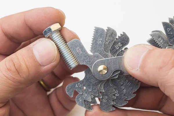
How to identify the thread on an old boltΠώς αναγνωρίζεται ένα άγνωστο σπείρωμα με παχύμετρο και σπειρώμετρο, σε πέντε βήματα.
StraightedgesChecking straightness and flatness of surfaces per DIN 874.
Gauge BlocksStandard length gauge blocks for calibration and setting.
Precision Squares DIN 875Checking 90° squareness with precision squares.
Κατηγορίες Ακρίβειας Γωνιών: DIN 875Accuracy grades of 90° squares per the DIN 875 standard.
Surface PlatesGranite or cast-iron reference plates for flatness checking.