
Micrometers
Correct use for precision measurement.
What a micrometer is
Together with the caliper, the micrometer is the most widely used precision measuring instrument, and a standard tool in mechanical engineering. It is built so that the measuring force is always the same. This is done by the ratchet stop, which slips freely once the measuring force reaches the limit set by the manufacturer. That is why a micrometer is a more reliable measuring instrument than a caliper.
Key principle
Constant measuring force
The ratchet stop or friction thimble slips at a preset force, so every measurement is taken with the same pressure, whoever the operator is. This reduces error and makes measurements repeatable.

Types of micrometer
Micrometers are either digital or analogue.


How to read a micrometer
Resolution 0.01 mm
On micrometers with a resolution of one hundredth of a millimetre (0.01 mm), the reading is taken as in the image below.

Reading example
- On the sleeve, read the whole and half millimetres that are uncovered: e.g. 7 mm.
- On the thimble, read the line that lines up with the reference line: e.g. 32 → 32 × 0.01 = 0.32 mm.
- Total: 7 + 0.32 = 7.32 mm.
Watch out: if the half-millimetre line is also uncovered, the same thimble reading gives 7.82 mm, so always check whether the half-mm line has been passed.
With a vernier: 0.001 mm
The vernier scale (3) in the drawing makes it possible to measure to 0.001 mm.
As on a caliper, the vernier gives the last digit (here, the single µm): look for the vernier line that lines up with a line of the hundredths scale (0.01 mm).

With a counter: 0.001 mm

Sources of error
Thermal expansion from a bare hand

The graph above shows how micrometers of different sizes expand when held in a bare hand. Heat flowing from the hand into the frame can cause a considerable error through expansion. That is why some micrometers have plastic heat insulators on the frame. Otherwise, wearing gloves is recommended.
Supporting position

The table above shows the errors that occur when the micrometer is zeroed in the first supporting position (from below, at the centre) but measurements are then taken in a different position. Ideally, measure with the micrometer supported the same way as when it was zeroed.
The Abbe principle

The Abbe principle states that the highest accuracy is achieved when the graduated scale lies on the same axis as the measurement. Otherwise the tilt «θ» of the moving jaw (of a caliper, or a micrometer with jaws) causes an offset «ε» that the graduated scale does not register.
Measurement errors
Several factors can cause errors while measuring.
- Error in the spindle screw.
- Flatness and parallelism error of the measuring faces.
- Excessive measuring force.
Checking micrometer parallelism with optical parallels
The parallelism of the measuring faces can be checked with optical parallels. First bring the parallel into contact with one face, then close the other face onto it with the normal measuring force. Then count the fringes you can see. Each fringe represents a height difference of half a wavelength (0.32 µm for red fringes). In the example below, the parallelism is about 1 µm: 0.32 µm × 3 = 0.96 µm.

Checking micrometer flatness with optical parallels
The flatness of the measuring faces can also be checked with an optical parallel, by counting the red fringes seen on the face under white light. Each fringe represents a height difference of half a wavelength (0.32 µm for red fringes).

General tips for using a micrometer
Choose the type, range, resolution and so on carefully to suit the application.
Let the micrometer and the workpiece reach room temperature.
Look straight at the graduations, square to the scale, to avoid parallax error.

Clean both measuring faces by placing a piece of paper between them, closing them on it and then gently pulling the paper out.
Use the constant-force mechanism correctly.
When using a micrometer stand, clamp the micrometer at the centre of the frame. Do not overtighten.

Avoid knocking the micrometer against other objects or dropping it, and do not turn the ratchet with excessive force. If you think an instrument has been mistreated, you can always check it with gauge blocks and optical parallels.
Storage notes
Store in a ventilated place with low humidity.
Avoid dusty places.
When storing, leave a gap of about 0.1–1 mm between the measuring faces.
Do not store the micrometer in a stand.


← All guides

Related guides
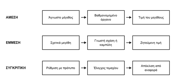
Direct, indirect and comparative measurementΟι διαφορές ανάμεσα στην άμεση, την έμμεση και τη συγκριτική μέτρηση, με παραδείγματα από διαστάσεις, ζύγιση και περιβάλλον.
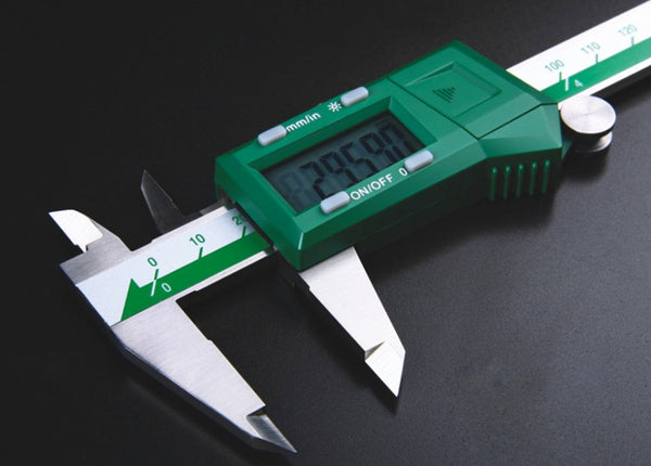
CalipersTypes, accuracy and how to choose the right caliper.
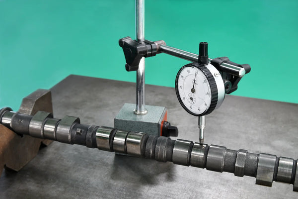
Dial IndicatorsΑναλογικά και ψηφιακά ρολόγια συγκριτικά με τη σωστή βάση.
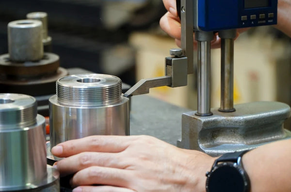
Height GaugesMeasuring and scribing height accurately on the surface plate.
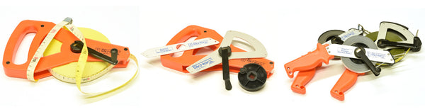
Measuring TapesAccuracy classes, materials and choosing for each use.
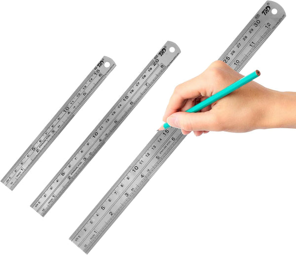
Steel RulesSteel rules and precision scales for lab and workshop.
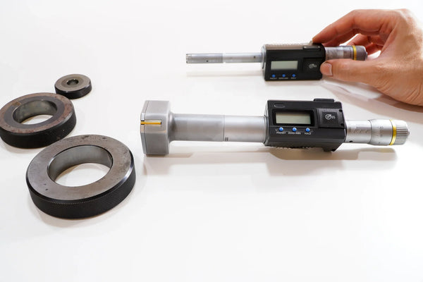
Bore Measurement InstrumentsAccurate internal bore measurement: types and methods.
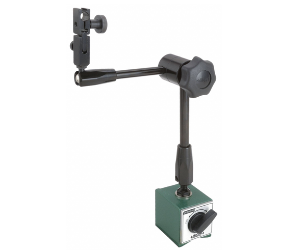
Magnetic BasesSturdy indicator holding stands with magnetic locking.
CalibrationsΤι αποδεικνύει ένα πιστοποιητικό, πώς εξασφαλίζεται η μετρολογική ιχνηλασιμότητα και πότε απαιτείται διαπιστευμένο εργαστήριο.