
Tolerance
Tolerance is the permissible deviation of a dimension from its nominal value, that is, how much a part may “play” and still count as acceptable. It is defined as the total permissible variation, the difference between the upper and the lower acceptable dimension limit, and it is always an absolute value.
Example: for a part specified as “20 ±0.1 mm”, every piece from 19.90 to 20.10 mm is within spec. These two extremes are the limits, the nominal value (20 mm) is the basic size, and the tolerance is their difference: 20.10 − 19.90 = 0.2 mm.
Depending on how it is distributed around the basic size, the tolerance is:
Bilateral: in both directions, e.g. 20 ±0.1.
Unilateral: in one direction only, e.g. 20 +0.2/−0 or 20 +0/−0.2, common in precision fits.
In practice tolerances are not set arbitrarily· they follow standardised systems (e.g. ISO 286, with codes such as H7/g6).
Tolerance is essentially a compromise: the tighter it is, the better the part functions, but the more expensive it is to make. So it is set as loose as the function allows, no tighter.
The common misconception
Tolerance concerns the part and the drawing (what I allow to be manufactured), not the instrument. Accuracy and uncertainty concern how well I measure. Practical rule: the instrument must be significantly more accurate than the tolerance it checks· typically the measurement uncertainty should be a small fraction of the tolerance.
In production, the quick “in/out of tolerance” check is often done with go/no-go limit gauges: the “go” side must pass, the “no-go” must not· that confirms the dimension sits between the two limits without even reading a number.
← All guides
Related guides
ResolutionΔιακριτική ικανότητα (Resolution) Η μικρότερη μεταβολή του μετρούμενου μεγέθους που μπορεί να διακρίνει και να εμφανίσει ένα όργανο.
TraceabilityH ιχνηλασιμότητα είναι αυτό που κάνει τις μετρήσεις συγκρίσιμες και αποδεκτές παντού
CalibrationΕίναι η διαδικασία που συγκρίνει τις ενδείξεις ενός οργάνου με τις τιμές ενός προτύπου (standard) υπό καθορισμένες συνθήκες
RepeatabilityΔείχνει πόσο κοντά μεταξύ τους βγαίνουν οι μετρήσεις όταν μετράμε το ίδιο αντικείμενο πολλές φορές
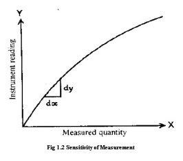
SensitivityΔείχνει πόσο αλλάζει η ένδειξη του οργάνου για μια δεδομένη μεταβολή του μετρούμενου μεγέθους.
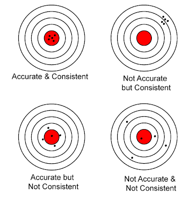
AccuracyΔείχνει πόσο κοντά είναι η μετρούμενη τιμή στην πραγματική (αληθή) τιμή του μεγέθους.
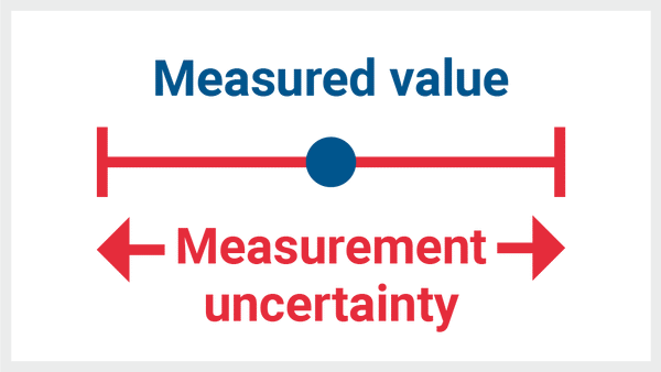
Measurement uncertaintyΗ αριθμητική εκτίμηση του εύρους μέσα στο οποίο βρίσκεται λογικά η πραγματική τιμή, το «±» κάθε σωστής μέτρησης.
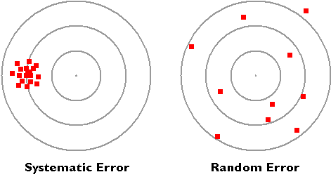
Systematic & random errorΗ διαφορά ανάμεσα στη μετρούμενη και στην πραγματική τιμή. Το συστηματικό μετατοπίζει τις μετρήσεις, το τυχαίο τις σκορπίζει.
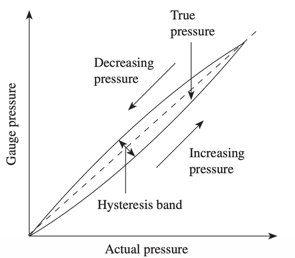
Υστέρηση (Hysteresis)Γιατί η ένδειξη ενός οργάνου αλλάζει ανάλογα με τη φορά της κίνησης.
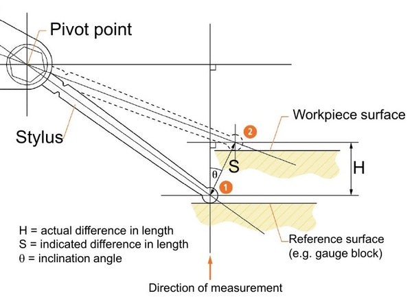
Cosine errorΓιατί η λοξή τοποθέτηση του οργάνου αλλοιώνει τη μέτρηση.
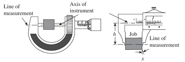
The Abbe principle and Abbe errorΗ αρχή του Abbe ορίζει ότι μέγιστη ακρίβεια επιτυγχάνεται μόνο όταν η κλίμακα μέτρησης (το πρότυπο) βρίσκεται στην ίδια ευθεία με τον άξονα της διάστασης που μετράμε.
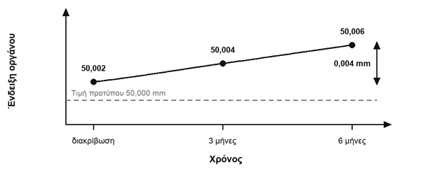
Drift and stabilityΗ μεταβολή της ένδειξης ενός οργάνου με τον χρόνο, χωρίς αντίστοιχη μεταβολή του μετρούμενου μεγέθους.
Dead band and backlashΓιατί μια μικρή μεταβολή ή η αντιστροφή της κίνησης μπορεί να μην εμφανιστεί αμέσως στην ένδειξη.